Search filter
Filter
Reset- Product data sheet (892)
- Installation drawing (888)
- Installation instructions (358)
- Tender texts (296)
- 3D model (181)
- Product scale drawing (147)
- Certificate (113)
- Declarations of performance (91)
- Cable plan (76)
- Declaration of conformity (73)
- Wiring diagram (43)
- Product declaration (LEED, DGNB, EPD) (43)
- User manual (35)
- Flyer/folder (28)
- Supplementary sheet (25)
- Product brochure (22)
- Type examination certificate (11)
- T&C / Data Protection (7)
- Software (5)
- Supplier information (4)
- Customer information (3)
- Safety analysis (2)
- Evaluation/comment (2)
3345 results found
ECturn door leaf installation hinge side link arm
PDF | 315 KB

TSA 160 NT
DWG | 118 KB
TSA 325 NT revolving door
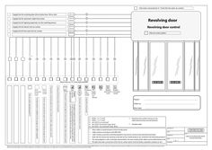
Hot water connection2x ¾ " (inch) (for hot water air curtain) Supply line for revolving door drive (mains fuse 10A on site) 230 V AC Supply line for automatic night-time closer 230 V AC Supply line for lighting (optional), on-site switching device 230 V AC Supply line for electric hot-air curtain 400 V AC Supply line for hot water hot-air curtain 230 V AC * * * * l l l l l j j j … j … n ll l Revolving door Revolving door control Hot-air curtain system l l l l l Please enter an “X” in the required elds! DPS DPS SCT Emergency TPS stop switch outside SCT optional TPS Disabled Disabled push button push button inside outside only with on-site position Via building management system DPS+2 control impulses (provided on site). It must be guaranteed that the revolving door with motor is switched off before the night-time closer opens or closes. Automatic night-time closer with dead man's control Control automatic night-time closer Reed contact Final position monitoring night-time closer (number of cables, cables product-speci c) Locking monitoring turnstile revolving door Final position monitoring night-time closer (number of cables, cables product-speci c) Hot-air curtain contact Hot-air curtain potential-free signal contact for building management system If a thermostat is installed on the canopy, no cable is required Hot-air curtain operating panel (*) Room thermostat on the inside Project: … Order no.: … Door type: … j k l m n NYM-J … x … mm² NYM-J … x … mm² JE-Y (ST)Y … x … x … mm² JE-Y (ST)Y 10 x … mm² (max. 20 m) JE-Y (ST)Y … x … x … mm² (max. 20 m) · Allow cables to stand at least … m from transfer point. · Cable routing in accordance with VDE 0100 · Cable routing, connection and initial operation may only be carried out by authorised specialists. · GEZE will not assume any warranty or provide service if GEZE products are combined with third-party products. · The wiring diagram is only a schematic representation. The exact routing of the cables must be determined . on site. · All cable and water connections of the hot-air curtain system must be laid by a specialist company on site. . … Determine the number of wires on site, cable dimensioning, terminal diameter. * Shielded cable PREPARED BY This drawing corresponds to the development status of the drawing date or the last revision. No claims of any kind, including damage claims, can be derived and asserted against GEZE GmbH from use of the drawing. The drawing remains the property of GEZE and is only provided to third parties for use during the contractual period. GEZE is exclusively entitled to all the claims resulting from the drawing. This drawing may not be duplicated nor made accessible to third parties without prior agreement by GEZE. . DATE TITLE REVISED ON CABLE PLAN REVOLVING DOOR CEILING MOUNTING PAGE … of … FILE NAME
PDF | 1 MB
ECturn door leaf installation hinge side guide rail
DOCUMENT | 6 MB
Standard cable plan Slimdrive EMD Invers 1-leaf pulling right hand door
DWG | 255 KB
Declaration of conformity GEZE GC 333 C
PDF | 73 KB
Sensor rail for GC 338 and Powerturn
Sensorschiene für GC 338 und Powerturn Sensorschiene für GC 338 und Powerturn 158559-01-0 DE Montageanleitung GB Mounting instructions Sensorrollenschiene für GC 338 und Powerturn Inhaltsverzeichnis Symbole und Darstellungsmittel / Symbols and means of representation … Produkthaftung / Product liability … Mitgeltende Dokumente / Additionally applicable documents … 1 Sicherheit / Safety … Bestimmungsgemäße Verwendung / Intended use … Sicherheitshinweise / Safety instructions … Sicherheitsbewusstes Arbeiten / Safety-conscious working … Umweltbewusstes Arbeiten / Environmentally-conscious working … 2 Beschreibung / Description … 3 Arbeiten vor der Montage / Arbeiten vor der Montage … 4 Montage / Mounting … Symbole und Darstellungsmittel / Symbols and means of representation Warnhinweise / Warnings In dieser Anleitung werden Warnhinweise verwendet, um Sie vor Sach- und Personenschäden zu warnen. XX Lesen und beachten Sie diese Warnhinweise immer. XX Befolgen Sie alle Maßnahmen, die mit dem Warnsymbol und Warnwort gekennzeichnet sind. In these instructions, warnings are used to warn against material damage and injuries. XX Always read and observe these warnings. XX Observe all the measures that are marked with the warning symbol and warning word. Warnwort / Warning word Bedeutung / Meaning Informationen zur Vermeidung von Sachschäden. VORSICHT CAUTION Information on avoiding property damage Symbole und Darstellungsmittel / Symbols and means of representation Um die korrekte Bedienung zu verdeutlichen, sind wichtige Informationen und technische Hinweise besonders herausgestellt. Important information and technical notes are emphasised in order to illustrate the correct operation. Symbol Bedeutung / Meaning bedeutet „Wichtiger Hinweis“ means “important note” bedeutet „Zusätzliche Information“ means “additional information” XX Symbol für eine Handlung: Hier müssen Sie etwas tun. XX Halten Sie bei mehreren Handlungsschritten die Reihenfolge ein. Symbol for an action: Here you have to do something. XX Observe the sequence if there are several action steps. Produkthaftung / Product liability Gemäß der im Produkthaftungsgesetz definierten Haftung des Herstellers für seine Produkte sind die in dieser Broschüre enthaltenen Informationen (Produktinformationen und bestimmungsgemäße Verwendung, Fehlgebrauch, Produktleistung, Produktwartung, Informations- und Instruktionspflichten) zu beachten. Die Nichtbeachtung entbindet den Hersteller von seiner Haftungspflicht. In accordance with the liability of manufacturers for their products as defined in the German “Produkthaftungsgesetz” (Product Liability Act), the information contained in this brochure (product information and proper use, misuse, product performance, product maintenance, obligations to provide information and instructions) is to be observed. Non-compliance releases the manufacturer from its statutory liability. … Sensorrollenschiene für GC 338 und Powerturn Sicherheit / Safety Mitgeltende Dokumente / Additionally applicable documents Art / Type Montageanleitung / Mounting instructions Name GC338 Die Anleitungen unterliegen Änderungen. Nur den neuesten Stand verwenden. The instructions are subject to change. Use only the most recent versions. … Sicherheit / Safety … Bestimmungsgemäße Verwendung / Intended use Die Sensorrollenschiene darf ausschließlich zur Montage der Sensorleiste verwendet werden. Anderer Einsatz als der bestimmungsgemäße Gebrauch sowie alle Veränderungen am Produkt sind unzulässig. The guide rail for sensor may only be used to mount the sensor strip. Any other use than the proper use as well as all changes to the product are impermissible. … Sicherheitshinweise / Safety instructions àà Vorgeschriebene Montage, Wartungs- und Instandsetzungsarbeiten müssen von Sachkundigen durchgeführt werden, die von GEZE autorisiert sind. àà Für sicherheitstechnische Prüfungen sind die länderspezifischen Gesetze und Vorschriften zu beachten. àà Eigenmächtige Änderungen an der Anlage schließen jede Haftung von GEZE für resultierende Schäden aus und die Zulassung für den Einsatz in Flucht- und Rettungswegen erlischt. àà Bei Kombination mit Fremdfabrikaten übernimmt GEZE keine Gewährleistung. àà Für Reparatur- und Wartungsarbeiten dürfen nur GEZE-Originalteile verwendet werden. àà Den neuesten Stand von Richtlinien, Normen und länderspezifischen Vorschriften beachten, insbesondere: àà DIN 18650 „Schlösser und Beschläge – Automatische Türsysteme“ àà Unfallverhütungsvorschriften, insbesondere BGV A1 „Grundsätze und Prävention“ und BGV A3 DA „Durchführungsanweisungen zur Unfallverhütungsvorschrift „Elektrische Anlagen und Betriebsmittel“ àà The prescribed mounting, maintenance and repair work must be performed by properly trained personnel authorised by GEZE. àà The country-specific laws and regulations are to be observed during safety-related tests. àà GEZE shall not be liable for injuries or damage resulting from unauthorised modification of the equipment, and the approval for use in escape and rescue routes is voided when unauthorised changes are made. àà GEZE shall not be liable if products from other manufacturers are used with GEZE equipment. àà Only original GEZE parts may be used for repair and maintenance work. àà Observe the latest versions of guidelines, standards and country-specific regulations, in particular: àà DIN 18650 “Building hardware – Powered pedestrian doors” àà Unfallverhütungsvorschriften, insbesondere BGV A1 „Grundsätze und Prävention“ und BGV A3 DA „Durchführungsanweisungen zur Unfallverhütungsvorschrift „Elektrische Anlagen und Betriebsmittel“ … Sicherheitsbewusstes Arbeiten / Safety-conscious working àà àà àà àà Arbeitsplatz gegen unbefugtes Betreten sichern. Schwenkbereich langer Anlagenteile beachten. Haube/Antriebsverkleidungen gegen Herunterfallen sichern. Bei Glasflügeln Sicherheitsaufkleber anbringen. àà Verletzungsgefahr bei geöffnetem Antrieb. Durch sich drehende Teile können Haare, Kleidungsstücke, Kabel usw. eingezogen werden! àà Verletzungsgefahr durch nicht gesicherte Quetsch-, Stoß-, Scher- und Einzugstellen! àà Verletzungsgefahr durch Glasbruch! àà Verletzungsgefahr durch scharfe Kanten im Antrieb! àà Verletzungsgefahr durch frei bewegliche Teile während der Montage! àà àà àà àà Protect the workplace against unauthorised entry. Take the swinging area of long system parts into account. Secure the hood/drive shrouding against falling. Attach safety labels to glass door leaves. àà Danger of injury at an opened drive. Hair, clothing, cables, etc. can be drawn in by rotating parts! àà Danger of injury by unsecured pinching, impact, drawing-in or shearing spots! … Beschreibung / Description Sensorrollenschiene für GC 338 und Powerturn àà Danger of injury by broken glass! àà Danger of injury by sharp edges in the drive! àà Danger of injury during mounting by freely moving parts! … Umweltbewusstes Arbeiten / Environmentally-conscious working àà Bei der Entsorgung der Türanlage die verschiedenen Materialien trennen und der Wiederverwertung zuführen. àà When disposing of the door system, separate the different materials and have them recycled. … Beschreibung / Description Die Sensorrollenschiene ermöglicht die Montage der Sensorleiste auf anstatt unter der Gleitschiene in Verbindung mit dem Powerturn. Dadurch kann platzsparender gebaut werden, die Sensorleiste ragt z. B. nicht mehr in die Glasfläche der Tür hinein. The guide rail for sensor allows the mounting of the sensor strip onto instead of under the guide rail in combination with the Powerturn. This allows space-saving construction so that for example the sensor strip no longer projects into the glass surface of the door. … 2 … 4 Sensorrollenschiene Sensorleiste Endkappe für Sensorrollenschiene … 2 … Sensorrollenschiene Sensor strip End cap for guide rail for sensor Sensorrollenschiene für GC 338 und Powerturn … Arbeiten vor der Montage / Arbeiten vor der Montage Arbeiten vor der Montage / Arbeiten vor der Montage Die Sensorleiste darf beim Öffnen der Tür nicht an der Wandlaibung anstoßen. XX Ggf. eine Wandaussparung (siehe Pfeil) vorsehen. oder XX Sensor bzw. Sensorrollenschiene bandseitig kürzen, soweit der Fahrbereich des Rollenhebels in der Gleitschiene dies zulässt. When opening the door, the sensor strip may not strike against the wall reveal. XX If necessary, prepare a recess (see arrow) in the wall. or XX Cut the guide rail for sensor to length on the hinge side as far as the movement range of the roller lever in the guide rail does allow. Montage / Mounting XX XX Sensorleiste (1) und Sensorrollenschiene (3) auf gewünschtes Maß zusägen. Äußere Bohrungen (2) in Sensorrollenschiene (3) setzen. Bohrrille (5) benutzen. XX XX Damit die Sensorrollenschiene (3) bei einer Länge von mehr als 1000 mm im Betrieb nicht vom Türblatt abhebt: XX Zusätzliche Bohrung (4) im Abstand 710 mm vom Türband setzen. Saw the sensor strip (1) and the guide rail for sensor (3) to the desired dimension. Place outer holes (2) in the guide rail for sensor (3). Bohrrille (5) benutzen. To ensure that the guide rail for sensor (3) does not lift up from the door leaf during operation when the length exceeds 1000 mm: XX Zusätzliche Bohrung (4) im Abstand 710 mm vom Türband setzen. … Montage / Mounting XX XX XX XX XX Sensorrollenschiene für GC 338 und Powerturn Rollenbolzen (6) in die Sensorrollenschiene (3) einfahren. Öffnungsbegrenzer (optional) einfahren (siehe separate Anleitung). Rollenbolzen (6) in die Sensorrollenschiene (3) einfahren. Öffnungsbegrenzer (optional) einfahren (siehe separate Anleitung). Distanzblöcke (7) links und rechts auf die Sensorrollenschiene (3) setzen. XX Bei Profilen > 1000 mm Distanzblock (7a) in die Mitte des Profils montieren. XX Distanzblöcke (7) links und rechts auf die Sensorrollenschiene (3) setzen. XX Bei Profilen > 1000 mm Distanzblock (7a) in die Mitte des Profils montieren. XX Je nach Beschaffenheit der Tür Sensorrollenschiene (3) mit beiliegenden Schrauben (8) (Spax bzw. metrische Schrauben) festschrauben. XX Depending on the nature of the door screw the guide rail for sensor (3) on using the enclosed screws (8) (Spax or metric screws). XX XX XX XX Äußere Bohrungen Ø … (10) in Sensorleiste (9) setzen. Bohrrille (5) benutzen. Place outer holes Ø … (10) in the sensor strip (9). Bohrrille (5) benutzen. … Sensorrollenschiene für GC 338 und Powerturn XX XX XX XX Montage / Mounting Sensorleiste (9) mit Schrauben M5 × 10 (11) auf Sensorrollenschiene (3) schrauben. Weitere Schritte siehe Montageanleitung GC338. Sensorleiste (9) mit Schrauben M5 × 10 (11) auf Sensorrollenschiene (3) schrauben. Weitere Schritte siehe Montageanleitung GC338. VORSICHT! Schäden am Rollenhebel, der in der Sensorrollenschiene läuft. XX Sicherstellen, dass keine Schrauben oder Schraubenköpfe in den Fahrbereich des Rollenhebels (14) ragen. CAUTION! Damages to the roller lever that runs in the guide rail for sensor. XX Make sure there is no protruding screws or screw heads in the movement range of the roller lever (14). XX Darauf achten, dass Kabel (12) nur im Durchgangsbereich (13) durch die Sensorrollenschiene (3) verlegt werden. Niemals im Bewegungsbereich des Rollenhebels (14) verlegen. XX Make sure that cables (12) are only routed in the lead-through area (13) of the guide rail for sensor (3). Never place cables in the movement area of the roller lever (14). XX 14 13 … 12 … Germany GEZE Sonderkonstruktionen GmbH Planken … 97944 Boxberg-Schweigern Tel. +49 (0) 7930 9294 … Fax +49 (0) 7930 9294 10 E-Mail: sk.de@geze.com GEZE GmbH Niederlassung Süd-West Tel. +49 (0) 7152 203 594 E-Mail: leonberg.de@geze.com GEZE GmbH Niederlassung Süd-Ost Tel. +49 (0) 7152 203 6440 E-Mail: muenchen.de@geze.com GEZE GmbH Niederlassung Ost Tel. +49 (0) 7152 203 6840 E-Mail: berlin.de@geze.com GEZE GmbH Niederlassung Mitte/Luxemburg Tel. +49 (0) 7152 203 6888 E-Mail: frankfurt.de@geze.com GEZE GmbH Niederlassung West Tel. +49 (0) 7152 203 6770 E-Mail: essen.de@geze.com GEZE GmbH Niederlassung Nord Tel. +49 (0) 7152 203 6600 E-Mail: hamburg.de@geze.com GEZE Service GmbH Tel. +49 (0) 1802 923392 E-Mail: service-info.de@geze.com GEZE GmbH Reinhold-Vöster-Straße 21–29 71229 Leonberg Germany Austria GEZE Austria E-Mail: austria.at@geze.com www.geze.at Hungary GEZE Hungary Kft. E-Mail: office-hungary@geze.com www.geze.hu Scandinavia – Denmark GEZE Danmark E-Mail: danmark.se@geze.com www.geze.dk Baltic States GEZE GmbH Baltic States office E-Mail: office-latvia@geze.com www.geze.com Iberia GEZE Iberia S.R.L. E-Mail: info@geze.es www.geze.es Singapore GEZE (Asia Pacific) Pte, Ltd. E-Mail: gezesea@geze.com.sg www.geze.com Benelux GEZE Benelux B.V. E-Mail: benelux.nl@geze.com www.geze.be www.geze.nl India GEZE India Private Ltd. E-Mail: office-india@geze.com www.geze.in South Africa GEZE Distributors (Pty) Ltd. E-Mail: info@gezesa.co.za www.geze.co.za Italy GEZE Italia S.r.l E-Mail: italia.it@geze.com www.geze.it Switzerland GEZE Schweiz AG E-Mail: schweiz.ch@geze.com www.geze.ch GEZE Engineering Roma S.r.l E-Mail: roma@geze.biz www.geze.it Turkey GEZE Kapı ve Pencere Sistemleri E-Mail: office-turkey@geze.com www.geze.com Bulgaria GEZE Bulgaria - Trade E-Mail: office-bulgaria@geze.com www.geze.bg China GEZE Industries (Tianjin) Co., Ltd. E-Mail: chinasales@geze.com.cn www.geze.com.cn GEZE Industries (Tianjin) Co., Ltd. Branch Office Shanghai E-Mail: chinasales@geze.com.cn www.geze.com.cn GEZE Industries (Tianjin) Co., Ltd. Branch Office Guangzhou E-Mail: chinasales@geze.com.cn www.geze.com.cn GEZE Industries (Tianjin) Co., Ltd. Branch Office Beijing E-Mail: chinasales@geze.com.cn www.geze.com.cn France GEZE France S.A.R.L. E-Mail: france.fr@geze.com www.geze.fr Tel.: 0049 7152 203 … Fax.: 0049 7152 203 310 www.geze.com Poland GEZE Polska Sp.z o.o. E-Mail: geze.pl@geze.com www.geze.pl Romania GEZE Romania S.R.L. E-Mail: office-romania@geze.com www.geze.ro Russia OOO GEZE RUS E-Mail: office-russia@geze.com www.geze.ru Scandinavia – Sweden GEZE Scandinavia AB E-Mail: sverige.se@geze.com www.geze.se Scandinavia – Norway GEZE Scandinavia AB avd. Norge E-Mail: norge.se@geze.com www.geze.no Ukraine LLC GEZE Ukraine E-Mail: office-ukraine@geze.com www.geze.ua United Arab Emirates/GCC GEZE Middle East E-Mail: gezeme@geze.com www.geze.ae United Kingdom GEZE UK Ltd. E-Mail: info.uk@geze.com www.geze.com
PDF | 409 KB
CE declaration of conformity WRM & WRB-5
PDF | 163 KB
Standard cable plan Powerturn-F/ R 1-leaf BS right hand door
PDF | 65 KB
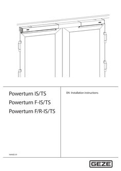
Powerturn IS-TS, Powerturn F-IS/TS, Powerturn F/R-IS/TS
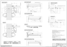
Powerturn IS/TS Powerturn F-IS/TS Powerturn F/R-IS/TS 164692-01 EN Installation instructions Powerturn F/R-IS/TS Contents … 1 Symbols and illustrations … 2 Product liability … 3 Security … Intended use … Standards … Reference documents … Safety notices … 4 Tools and aids … 5 Types of installation … Type of installation transom installation hinge side … Type of installation transom installation opposite hinge side … Types of installation, hinge action … Fitting dimensions for the installation types … 6 Product description … Illustrations of the TS 5000 L passive leaf unit … Illustrations of the TS 4000 passive leaf unit … 7 Installing the integrated Powerturn F closing sequence mechanism … 10 … Converting the TS units … 12 … TS 5000 L - conversion from DIN right to DIN left … 12 TS 4000 - conversion from DIN right to DIN left … 14 Connecting the mechanism for integrated closing sequence control of active and passive leaf … 15 Install carry bar … 20 Install hold-open magnet … 20 Installing the electrical contact for passive leaf position monitoring … 21 … Function check … 21 10 Commissioning … 21 11 Service and maintenance … 22 … General information … 22 Maintenance of mechanism for integrated closing sequence control … 22 12 Troubleshooting … 23 Powerturn F/R-IS/TS … Symbols and illustrations Symbols and illustrations Warning notices In these instructions, warning notices are used to warn against material damage and injuries. XX Always read and observe these warning notices. XX Observe all measures marked with the warning symbol and warning message . Warning symbol Warning message CAUTION Meaning Danger to persons. Non-compliance can result in minor injuries. More symbols and illustrations Important information and technical notes are highlighted to explain correct operation. Symbol Meaning means “important note” means “additional Information” XX … Symbol for an action: This means you have to do something. XX If there are several actions to be taken, keep to the given order. Product liability In compliance with the liability of the manufacturer for his products as defined in the German “Product Liability Act”, compliance with the information contained in this brochure (product information and intended use, misuse, product performance, product maintenance, obligations to provide information and instructions) must be ensured. Failure to comply releases the manufacturer from his statutory liability. … Security … Intended use The Powerturn F-IS/TS integrated closing sequence control has been designed for mechanical control during the closing of double-leaf single-action swing leaf doors. The construction components required are a supplement to the Powerturn drive and must be installed according to these instructions. The Powerturn F-IS/TS integrated closing sequence control àà is designed for use on fire and smoke protection doors. àà may be used on emergency exit systems. àà must not be used for hazardous areas. The Powerturn IS/TS integrated closing sequence control àà must not be used on fire or smoke protection doors. àà may be used on emergency exit systems. àà must not be used for hazardous areas. Any other use than the intended use, such as permanent manual operation of the Powerturn F, as well as any modification to the product, is not permitted. Observe the “GEZE Product information for door closers”. The product should be installed or incorporated in such a way that effortless access to the product is guaranteed during any repairs and/or maintenance, and that any removal costs do not stand out of proportion to the value of the product. … Standards In addition to the valid standards and regulations, DIN EN 1158 applies to the Powerturn. … Tools and aids … Powerturn F/R-IS/TS Reference documents àà Powerturn installation instructions àà Powerturn wiring diagram àà Installation instructions for Powerturn mechanism for integrated closing sequence control àà TS 5000 L installation instructions àà TS 4000 installation instructions àà Installation instructions carry bar àà Installation instructions and wiring diagram holdopen magnet àà User information door closer The diagrams are subject to change without notice. Use only the most recent version. … Safety notices The description of the overall installation of the drive is not the subject of these instructions. This information can be found in the Powerturn installation instructions. All the necessary safety notices for conversion or extension to a double-leaf version can be found on the following pages. … Tools and aids Tool Size Drill bit Ø … mm Open-ended spanner SW … Allen key … mm Allen key … mm Pozidrive screwdriver … Types of installation … Type of installation transom installation hinge side Active leaf … Type of installation transom installation opposite hinge side Passive leaf … Passive leaf Active leaf Powerturn F/R-IS/TS … Types of installation Types of installation, hinge action àà The opening angle of the door always has to be limited by a door stop buffer. àà Loads due to wind pressure, negative pressure or excess pressure must be taken into account. We recommend the installation type involving link arms (wind) for the exterior doors. The Powerturn IS/TS, Powerturn F-IS/TS, and Powerturn F/R-IS/TS permit, with respect to DIN left and DIN right, the following buffer stop types: … .1 Rail installation and link arm Type of installation Transom installation hinge side rail Dimension Reveal depth LT [mm] Door overlap Ü [mm] Max. door opening angle TÖW [°] 1) Standard roller guide rail L = [mm] Lever L = [mm] Hinge size [mm] EN class Max. door width [mm] Type of installation Dimension Transom installation opposite hinge side link arm Reveal depth SD standard and with sensor link arm [mm] Max. door leaf thickness [mm] Max. door opening angle TÖW [°] 1) Hinge size [mm] EN class Max. door width [mm] 1) Powerturn F TS 5000 L … 0–15 133 687 330 O 1600 180 415 333 190 4–6 Powerturn F O 1400 TS 4000 0–160 150 135 O 1600 180 190 4–7 O 1600 depending on the door construction and door hinges used For other limits of use see: àà Powerturn installation instructions àà TS 5000 L installation instructions àà TS 4000 installation instructions … Types of installation Powerturn F/R-IS/TS … Fitting dimensions for the installation types … .1 Type of installation transom installation hinge side … 2 … Dimensional reference - Centre of hinge/Upper edge of door Covered line-feed possible in the hatched area, e.g. Ø 20 mm for the mains connection or low-voltage connection Orientation arrow for precise positioning of the mounting plate Fastening means Steel/aluminium doors Timber doors … countersunk head screws M6 × 25 and riveting nuts M6 … wood screws with countersunk head Ø6 × 50 TS attachment … cylinder head screws M6 × 20 and riveting nuts M6 … wood screws with cylinder head Ø6 × 50 Intermediate base plate attachment … cylinder head screws M6 × 25 and riveting nuts M6 … wood screws with cylinder head Ø6 × 50 Fastening standard roller guide rail … countersunk head screws M5 × 40 and riveting nuts M5 … wood screws with Powerturn countersunk head Ø5 × 50 Fastening for the vertically adjustable … countersunk head screws M5 × 40 and riveting nuts M5 … wood screws with TS 5000 L guide rail countersunk head Ø5 × 50 Drive fastening Space requirement and fastening Standard roller guide rail Powerturn Sensor roller guide rail Powerturn Guide rail TS 5000 L 19 15 41 66 50 … 5 … 50 Base top edge of door Space requirement for sensors … 92 22 10 10 … 42 36 10 … 5 15 … 50 50 10 … 26 36 10 92 22 42 10 130 31 Powerturn F/R-IS/TS … .2 Types of installation Type of installation transom installation opposite hinge side Fastening - DIN right … 2 Fastening DIN left Dimensional reference centre of hinge/bottom edge of frame Covered line-feed possible in the hatched area, e.g. Ø 20 mm for the mains connection or low-voltage connection Orientation arrow for precise positioning of the mounting plate … Fastening means Steel/aluminium doors Timber doors … countersunk head screws M6 × 25 and riveting nuts M6 … wood screws with countersunk head Ø6 × 50 TS attachment … cylinder head screws M6 × 20 and riveting nuts M6 … wood screws with cylinder head Ø6 × 50 Intermediate base plate attachment … cylinder head screws M6 × 25 and riveting nuts M6 … wood screws with cylinder head Ø6 × 50 Fastening for the Powerturn link arm … cylinder head screws M6 × 16 and riveting nut M5 … wood screws with cylinder head Ø5 × 20 Fastening for the TS 4000 link arm … cylinder head screws M5 × 16 and riveting nut M5 … wood screws with cylinder head Ø5 × 20 Fastening the adapter for the Powerturn … countersunk head screws M6 × 20 and riveting nut M6 … wood screws with sensor link arm countersunk head Ø5 × 35 Drive fastening Space requirement and fastening Powerturn link arm Link arm TS 4000 11* … 5 * … 5 50 50 50 41 35 43 8* 72 … 10 50 46 42 22 10 130 Base lower edge of lintel Space requirement for sensors Important functional dimension … Product description Powerturn F/R-IS/TS … Product description … Illustrations of the TS 5000 L passive leaf unit … .1 TS 5000 L passive leaf unit transom installation hinge side DIN right Single side panel (for continuous cover) … 2 … .2 Double side panel (for split cover) Rocker for integrated closing sequence control Deflection pulley TS 5000 L passive leaf unit transom installation hinge side DIN left Single side panel (for continuous cover) … 2 … Rocker for integrated closing sequence control Deflection pulley Double side panel (for split cover) Powerturn F/R-IS/TS Product description … Illustrations of the TS 4000 passive leaf unit … .1 TS 4000 passive leaf unit transom installation opposite hinge side DIN right Single side panel (for continuous cover) … .2 Double side panel (for split cover) Rocker for integrated closing sequence control TS 4000 passive leaf unit transom installation opposite hinge side DIN left Single side panel (for continuous cover) … Double side panel (for split cover) Rocker for integrated closing sequence control … InstallingtheintegratedPowerturnFclosingsequencemechanism … Powerturn F/R-IS/TS Installing the integrated Powerturn F closing sequence mechanism … 2 SW … 7 … 5 … Nm … Transom installation opposite hinge side Transom installation hinge side Installation position brake unit: Opposite Hinge Side (OHS) Installation position brake unit: Hinge Side (HS) 10 Powerturn F/R-IS/TS InstallingtheintegratedPowerturnFclosingsequencemechanism … 1 Nm SW … Nm SW … 11 10 XX During installation of the setting lever, pay attention to the alignment of the mechanism for integrated closing sequence control (see below). Types of installation: àà Transom installation - hinge side, DIN left àà Transom installation - opposite hinge side, DIN right Types of installation: àà Transom installation - hinge side, DIN right àà Transom installation - opposite hinge side, DIN left 11 Converting the TS units Powerturn F/R-IS/TS … Converting the TS units … TS 5000 L - conversion from DIN right to DIN left This chapter describes the conversion work necessary if TS 5000 L is to have a DIN left installation. … .1 TS 5000 L is delivered for DIN right installation from the factory … .2 Converting the TS 5000 L 12 Powerturn F/R-IS/TS Converting the TS units 13 Converting the TS units … Powerturn F/R-IS/TS TS 4000 - conversion from DIN right to DIN left This chapter describes the conversion work necessary if TS 4000 is to have a DIN left installation. … .1 TS 4000 transom installation opposite hinge side is delivered for DIN right installation from the factory … .2 Converting the TS 4000 14 Powerturn F/R-IS/TS Converting the TS units … Connecting the mechanism for integrated closing sequence control of active and passive leaf XX XX Install the drive and lever. For drive installation, see installation instructions Powerturn, “prepare for installation” and “Installation” sections. For TS installation, see the chapter … . Installation of the guide rail and lever of the TS 5000 L-shaft and the adjustment of the valves, see TS 5000 L installation instructions. àà Installation of the link arm of the TS 4000 and the adjustment of the valves, see TS 4000 installation instructions. àà Use the pre-mounted screw in the TS 4000 shaft for fastening the link arm on the TS 4000-shaft. XX Use the pre-mounted screw in the TS 5000 L-shaft for fastening the lever, not the screw enclosed with the screw accessories for the TS 5000 guide rail. 15 Converting the TS units … .1 Powerturn F/R-IS/TS Mounting the door closer unit For the installation dimensions, see chapter … . TS 5000 L TS 4000 Connection of the active and passive leaf drive: Passive leaf (1) 16 Active leaf (2) Powerturn F/R-IS/TS Converting the TS units XX With continuous cover, remove the side panels. XX Drill the passage in the side panel for the split cover and deburr (depending on the route of the wire cable): Ø … mm Route of wire cable near the passive leaf unit: TS 5000 L DIN right TS 4000 DIN right TS 5000 L DIN left TS 4000 DIN left 17 Converting the TS units Powerturn F/R-IS/TS Route of wire cable near the control: Position of setting lever with the brake closed … 18 Motor Position of setting lever with the brake opened … Motor Powerturn F/R-IS/TS Converting the TS units Attach the wire rope and spring on the wire rope tensioner … 2 … ~ … Nm … SW … 2 Set screw (1), tension spring (2) ~ … Nm … 3 Position of the setting lever (3) = brake opened, active leaf closing. 19 Converting the TS units Powerturn F/R-IS/TS Set the retaining action of the integrated closing brake SW … The correct setting of the entire mechanism for integrated closing sequence control has been achieved when, with the brake closed and passive leaf closed, the setting lever takes up the position as designated for the open brake. The wire rope must be tensioned both with opened and closed integrated closing brake between the passive and active leaf unit. … Install carry bar CAUTION! Danger of crushing. Body parts can become caught between the door leaves XX Install carry bar. A carry bar must be installed in order to protect the main closing edge. XX Install the carry bar in compliance with the included installation instructions. … Install hold-open magnet A hold-open magnet must be installed for the hold-open function of the passive leaf. XX Install the hold-open magnet so as to ensure sufficient door opening. The hold-open magnet must be permanently and reliably attached to the building. XX Safeguard the connection cable between the hold-open magnet and the Powerturn against outside access. XX Connect the hold-open magnet in compliance with the included wiring diagram and the Powerturn wiring diagram, “Hold-open system Powerturn F-IS/TS, F/R-IS/TS” section. 20 Powerturn F/R-IS/TS … Function check Installing the electrical contact for passive leaf position monitoring To monitor the position of the passive leaf, the enclosed electrical contact must be installed on the passive leaf to ensure the proper function of the closing sequence control of the door leaves in the Powerturn’s automatic mode If necessary, information must be obtained from the door manufacturer if the passive leaf is mechanically treated for installation of the contact and wiring. See the wiring diagram, section “2-leaf drives” on connection of the contact to the Powerturn control. … Function check Open the active and passive leaves up to the waiting position. Release the passive and active leaves. The passive leaf must start the closing movement immediately. The active leaf must remain in position until the brake is opened by the mechanism for integrated closing sequence control on the passive leaf. The active leaf closes. Further test requirements: see national/international standards and regulations. XX XX 10 Commissioning àà àà àà àà For adjusting the Powerturn spring force, see the Powerturn installation instructions, “Settings” section. For spring force setting of the TS 5000 L and TS 4000, see the installation instructions TS 5000 L and TS 4000. For electrical connection, see the Powerturn wiring diagram, “Mains connection” section. The passive leaf must be closed for the Powerturn F/R-IS/TS teaching process. The Powerturn must be taught in as a single leaf door, see Powerturn wiring diagram, “Commissioning and service” section. àà The Powerturn parameters must be set on the basis of the specifications of the Powerturn wiring diagram, section “2-leaf drives”. These settings can be used to complete the electrical function test. 21 Service and maintenance 11 Service and maintenance … General information Powerturn F/R-IS/TS The maintenance work on the closing sequence control must be carried out by an expert during the maintenance cycle of the Powerturn drive. àà For maintenance instructions for the Powerturn swing door drive, see Powerturn installation instructions “Service and maintenance” section. àà For maintenance instructions for the door closer, see the door closer user information. … Maintenance of mechanism for integrated closing sequence control XX XX XX Clean hold-open magnet and test door hold-open capabilities. Check rope for integrated closing sequence control to ensure it is under tension; increase tension if needed or exchange wire rope if damaged. Check rocker for integrated closing sequence control for secure attachment to the door closer; tighten screw if needed or exchange the rocker for integrated closing sequence control if damaged. Check castor (1) in the rocker for integrated closing sequence control to ensure it moves and turns easily. If it is stiff, exchange the rocker for integrated closing sequence control and castor together. For TS 5000 L: XX Check the deflection pulley (2) for smooth function; lubricate and ensure smooth running function if needed. XX 22 Powerturn F/R-IS/TS 12 Troubleshooting Troubleshooting For troubleshooting and fault elimination see the fault table in the Powerturn wiring diagram, "Fault messages" section. 23 Germany GEZE GmbH Niederlassung Süd-West Tel. +49 (0) 7152 203 594 E-Mail: leonberg.de@geze.com GEZE GmbH Niederlassung Süd-Ost Tel. +49 (0) 7152 203 6440 E-Mail: muenchen.de@geze.com GEZE GmbH Niederlassung Ost Tel. +49 (0) 7152 203 6840 E-Mail: berlin.de@geze.com GEZE GmbH Niederlassung Mitte/Luxemburg Tel. +49 (0) 7152 203 6888 E-Mail: frankfurt.de@geze.com GEZE GmbH Niederlassung West Tel. +49 (0) 7152 203 6770 E-Mail: duesseldorf.de@geze.com GEZE GmbH Niederlassung Nord Tel. +49 (0) 7152 203 6600 E-Mail: hamburg.de@geze.com GEZE Service GmbH Tel. +49 (0) 1802 923392 E-Mail: service-info.de@geze.com Austria GEZE Austria E-Mail: austria.at@geze.com www.geze.at Hungary GEZE Hungary Kft. E-Mail: office-hungary@geze.com www.geze.hu Scandinavia – Sweden GEZE Scandinavia AB E-Mail: sverige.se@geze.com www.geze.se Baltic States – Lithuania / Latvia / Estonia E-Mail: baltic-states@geze.com Iberia GEZE Iberia S.R.L. E-Mail: info.es@geze.com www.geze.es Scandinavia – Norway GEZE Scandinavia AB avd. Norge E-Mail: norge.se@geze.com www.geze.no Benelux GEZE Benelux B.V. E-Mail: benelux.nl@geze.com www.geze.be www.geze.nl India GEZE India Private Ltd. E-Mail: office-india@geze.com www.geze.in Scandinavia – Denmark GEZE Danmark E-Mail: danmark.se@geze.com www.geze.dk Bulgaria GEZE Bulgaria - Trade E-Mail: office-bulgaria@geze.com www.geze.bg Italy GEZE Italia S.r.l E-Mail: italia.it@geze.com www.geze.it Singapore GEZE (Asia Pacific) Pte, Ltd. E-Mail: gezesea@geze.com.sg www.geze.com China GEZE Industries (Tianjin) Co., Ltd. E-Mail: chinasales@geze.com.cn www.geze.com.cn GEZE Engineering Roma S.r.l E-Mail: italia.it@geze.com www.geze.it South Africa GEZE South Africa (Pty) Ltd. E-Mail: info@gezesa.co.za www.geze.co.za GEZE Industries (Tianjin) Co., Ltd. Branch Office Shanghai E-Mail: chinasales@geze.com.cn www.geze.com.cn GEZE Industries (Tianjin) Co., Ltd. Branch Office Guangzhou E-Mail: chinasales@geze.com.cn www.geze.com.cn GEZE Industries (Tianjin) Co., Ltd. Branch Office Beijing E-Mail: chinasales@geze.com.cn www.geze.com.cn France GEZE France S.A.R.L. E-Mail: france.fr@geze.com www.geze.fr Korea GEZE Korea Ltd. E-Mail: info.kr@geze.com www.geze.com Poland GEZE Polska Sp.z o.o. E-Mail: geze.pl@geze.com www.geze.pl Romania GEZE Romania S.R.L. E-Mail: office-romania@geze.com www.geze.ro Russia OOO GEZE RUS E-Mail: office-russia@geze.com www.geze.ru Switzerland GEZE Schweiz AG E-Mail: schweiz.ch@geze.com www.geze.ch Turkey GEZE Kapı ve Pencere Sistemleri E-Mail: office-turkey@geze.com www.geze.com Ukraine LLC GEZE Ukraine E-Mail: office-ukraine@geze.com www.geze.ua United Arab Emirates/GCC GEZE Middle East E-Mail: gezeme@geze.com www.geze.ae United Kingdom GEZE UK Ltd. E-Mail: info.uk@geze.com www.geze.com GEZE GmbH Reinhold-Vöster-Straße 21–29 71229 Leonberg Germany Tel.: 0049 7152 203 … Fax.: 0049 7152 203 310 www.geze.com
PDF | 4 MB